The most distinct and unique feature of the Super Lower is the large support rib on the left side of the lower. This greatly increases the strength and stiffness of the buffer tower. Unfortunately another large rib cannot be added to the right side of the lower because it would interfere with the forward assist on many upper receivers. The result is that the right side becomes the the new weak spot of the buffer tower area. The main goal of V3.0 is to fix that – While still maintaining compatibility with a wide range of uppers.
Before we dig into the details I want to say, if you have already printed an older version of the Super Lower, such as V2.7 or V2.8, then I highly recommend you reprint with V3.0. The older versions worked great, and still will. But V3.0 is better. You can download the V3.0 files over on the downloads page.
I made several improvements with V3.0. One of them is that the bolt hold open area has been redesigned. But the most important change was the redesign of the right side. Below you can see a photo of V3.0.
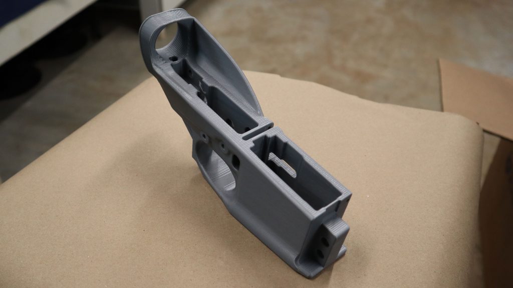
It may not look very different from older versions, but the change will be more obvious in the below photos.
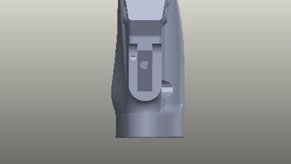
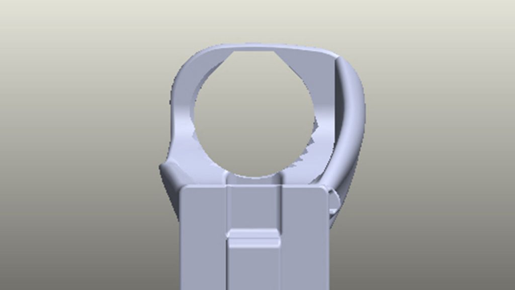
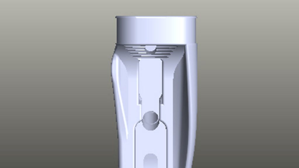
The weak spot on older versions was compounded by the rear take down pin hole resting very near to the surface on the right side, creating a stress riser that would further weaken the right side. In the above photos you can see that around an eighth inch of material has been added to the right side above where the rear take down pin hole ends. Also a small rib has been added above the right side that helps to increase strength, while not interfering with the forward assist.
The material has been added in such a way so as to not to effect function. The rear of the buffer tower has the same profile as older versions, so the same stocks and clamp will work fine.
Something that quite a number of people have requested is an ambidextrous lower. I don’t think an ordinary single ribbed lower would be strong enough if the right side was cut down to allow a ambidextrous selector switch to be used. However that does not mean there is not another way to do so.
I think that the best way to design an ambidextrous lower is to use two full sized reinforcement ribs, one on each side. This would have the caveat that only slick sided and side charging uppers could be used. But the extra rib on the right side would add enough strength that the right side below the rib could be made slim like the left side is now. And any ambi’ selector could be used at will. That’s a project to do after the AR-9 is done.
Of course these changes can, and should, also be made to the LR-308 Super Lower. That will problebly result in the V2.0 LR-308 Super Lower. Though no promises on when that will be released 😉
Let me know what changes you would like to see with the Super Lower. And be sure to download V3.0!
Looks good; makes sense.
I have only been into 3D printing for 6 months and it appears you are working hard and getting great results, cant wait for the AR9, keep up the great work and the R&D
Sam Dunston
Looks good .
You should look into using a wire clamp insted of the hose clamp. No bulky part sticking out. The ones that wrap a pair of wires arond one or two times and bend back over themselves to clamp.
Ive actually been using some fiberglass reinforced banding tape for the buffer section reinforcement.
3 lowers so far with at least 400 rds a piece. absolutely 0 issues.
After following your advice about the 100.3 percent print scale, the fitment is ridiculous. takes 5 minutes from the print finishing and the entire lower is done.
Awesome!
The “Lets go Brandon” easter egg made me laugh. Thanks!
Let’s go Brandon!
I busted out laughing when I saw that too
Would it be possible to add a support on the right side for guys that run a slick side upper without the forward assist?
Absolutely! It’s on the list.
Have you thought about using a single rectangular brass bar (per side) for both the trigger and hammer pins? Seems that might help even more to keep them positively located, and distribute the load more.
Keep up the great work!
I actually have not. It’s an interesting idea though. But the plates would cost a lot more to make then the bushings.
What size brass bushings do you use? Outer diameter and thickness??
Awesome work by the way!
I have them custom made. They are 0.375″ OD, 0.156″ ID and 0.100 THK.
Are there curtain pins I have to use for this lower ? I bought a lower parts kit and my pins are too small. Plus the grip screw won’t thread it just goes straight threw the hole so it doesn’t secur it properly
Easy to explain 😉 You must have printed the Super Lower. It is designed to fit brass bushings for the pins, you can see the pockets on the inside. It also is designed to use a threaded insert for the grip screw. These are parts I sell in the Reinforcement Kit.
Take a look at the Basic Lower. It is designed to not need these parts.
Is there somewhere you published all of the Prusa Slicer settings for the Push Plastic CFN?
I’ve not done so yet. It’s just my basic print settings but with different temps.
First off, thanks for a brilliant design, love the structural modifications. Just printed a v3.0 and got the parts kit as well (another kuddo for your fast shipping!) I noticed that the fire control pin holes aren’t recessed for the brass bushings, are they not needed any longer?
Also, have you looked into annealing the lowers to increase strength? There is some dimensional shifting but the larger increase in strength due to removing the internal stresses might be worth the trouble of figuring out the scaling issues.
BJH
You must be looking at the “Basic” version, which does not have bushing pockets. I’m still running bushings on all the Super Lowers.
Annealing is definitely on he list! I have experimented a little, but found warping / shrinkage to be a problem. More work is needed.
You’re right, I had a brain cramp and printed the wrong file. The right file worked a charm.
As for annealing, I mounted the lower on a stripped metal upper and sat it in the oven upside down. No warping issues.
Is there a reason you opted for a threaded insert for the grip screw instead of just leaving an inset for a hex nut like many of the cast polymer lowers use?
Can you make a print settings video how do you get your prints so clean?
It doesn’t have to be ambidextrous. Just make a reverse of the lower for left handed people.
for the ar9 do you still need the ar15 reinforcement kit + pin ?>
Yes. You need the roll pin and the AR-15 Reinforcement Kit. You will also need to source your own heavy AR-9 buffer.
To the Hoffman team: Amazing work! You guys are incredible, and such an asset to the community.
Regarding strengthening the buffer ring – it seems like it could be reinforced somewhat by printing a channel for either a wire or other reinforcing material that could take the load without flexing as much.
Examples of this type of scheme:
https://youtu.be/XpDG8VxZsw4 (1mm steel wire) – He used a soldering iron to heat the wire and push it into the channel in the part so it fit nice and tight. Very clever.
https://youtu.be/iICk_ZpY4Cs – A later version of his testing used epoxy to bed carbon fiber filament.
I’m not certain how much breakage people are having, but IF buffer tower strength maximization is the goal, it seems hard to beat this type of fairly straightforward modification. Could be AMAZINGLY strong with the dual-rib setup for slick-sides.
Would be interesting if anyone’s tried modifying these lowers in this way, or if there are any official plans to support something like this.